Cableado RS485 de la serie Autarco LQ
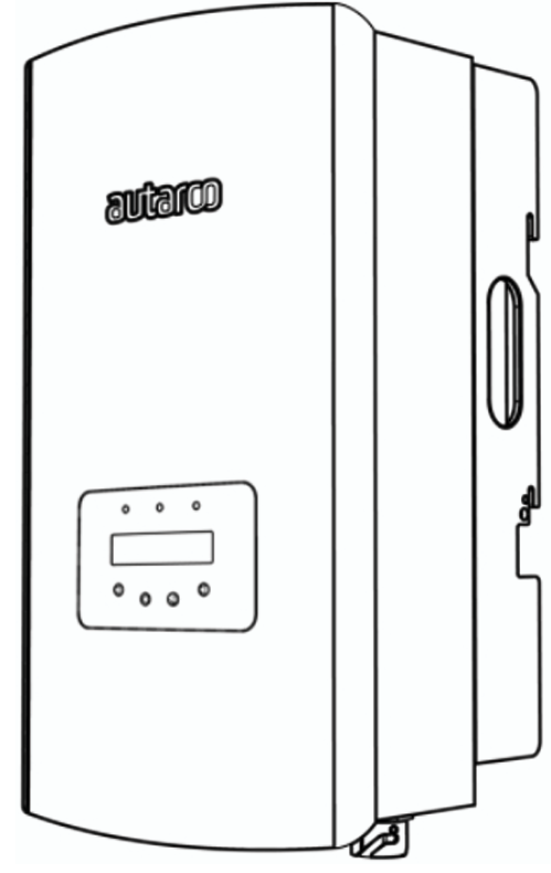
Esta página describe la comunicación con un inversor híbrido de la serie LQ de Autarco a través de Modbus-RTU (rs485). Por defecto, el inversor está configurado en la dirección 1. La interfaz RS485 es un conector de 4 pines en la parte inferior del inversor detrás de una placa protectora. La posición exacta está marcada en el cuadro naranja en la imagen a continuación:
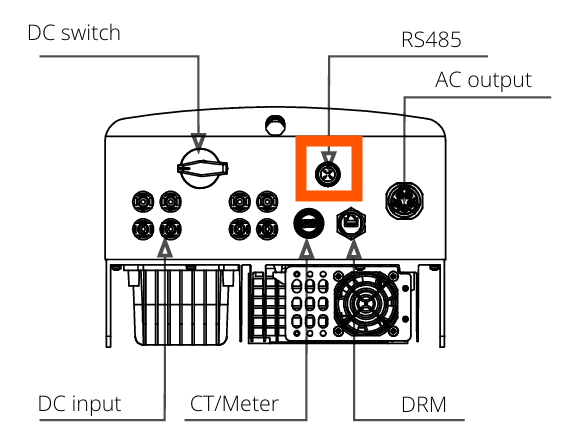
Al mirar más de cerca, el puerto se ve así:

Se debe utilizar un conector apropiado para este conector de 4 pines en el inversor Autarco para conectarse al SmartgridOne Controller. En el SmartgridOne Controller, el inversor se puede conectar al puerto RS485. El cableado es el siguiente:
RS485 Wiring
- For correct RS485 wiring: Follow the guidelines for RS485 wiring.
- If the wiring shown in the table below is incorrect, please let us know.
- There is no general consensus in the industry about the usage of A and B for the RS485 polarity, so it may be counterintuitive and opposite of what you might expect for some devices.
| Device | SmartgridOne Controller model OM1 | SmartgridOne Controller model IG8 | RS485-USB converter | RS485-Ethernet converter |
|---|---|---|---|---|
| Pin 3 | RS485 A | RS485_POS | RS485 A | TX+ |
| Pin 4 | RS485 B | RS485_NEG | RS485 B | TX- |
| N/A | RS GND | GND | Not available | G |
NOTE: RS485 Device Addresses
- You MUST give each device on the RS485 bus a unique address. Check the manual of the device on how to do this.
- Use lower addresses first (1, 2, ...) because the SmartgridOne Controller will find them faster!
- For each device, it is generally recommended to stick with the factory default baud rate, parity, and stop bits. The SmartgridOne Controller will scan on those first.