DEYE
Appareils pris en charge
| Device Type | Variants | Modbus TCP (Ethernet) | RS485 | Curtailment |
|---|---|---|---|---|
| Inverseurs hybrides monophasés LV (SG0XLP1-EU) | SUN-3/3.6/5/6/7/7.6/8/10/12K | ❌ | ✅ | ❌ |
| Inverseurs hybrides triphasés LV (SG0XLP3-EU) | SUN-3/4/5/6/8/10/12/14/15/16/18/20K | |||
| Inverseurs hybrides triphasés HV (SG0XHP3-EU) | SUN-5/6/8/10/12/15/20/25/29.9/30/35/40/50/60/70/75/80K | |||
| Inverseurs string monophasés (G0XP1-EU) | SUN-1/1.5/2/2.2/2.5/2.7/3/3.3/3.6/4/4.2/4.6/5/5.2/6/6.2/7/7.5/8/9/10/10.5K | |||
| Inverseurs string triphasés (G0XP3-EU) | SUN-3/4/5/6/7/8/9/10/12/15/18/20/22/23/25/30/35/36/40/45/50/60/70/75/80/90/100/120/125/130/135/136K |
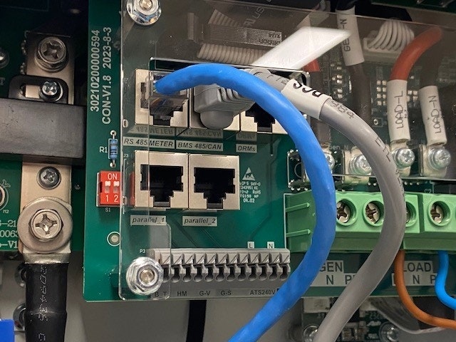
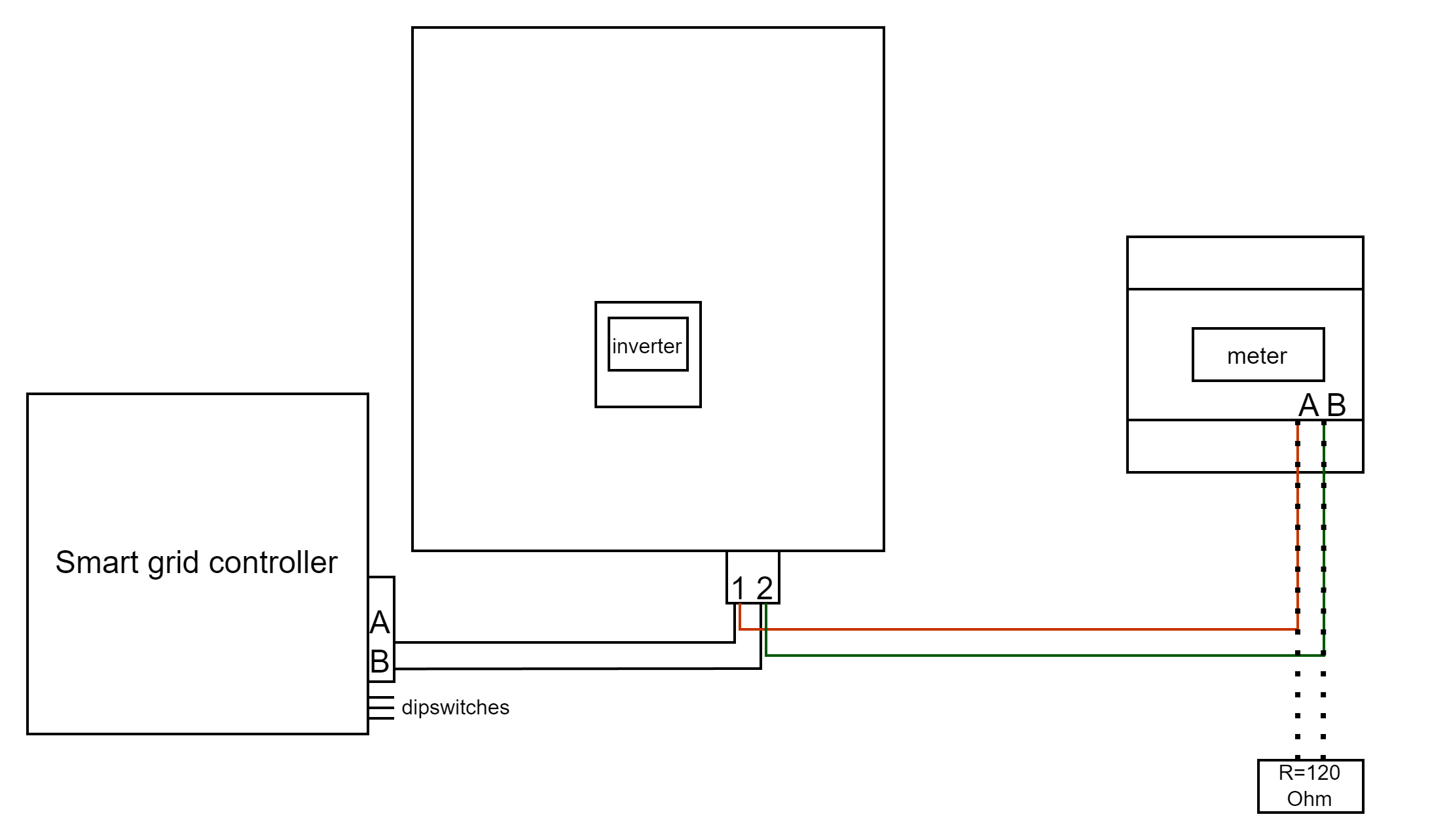
Câblage
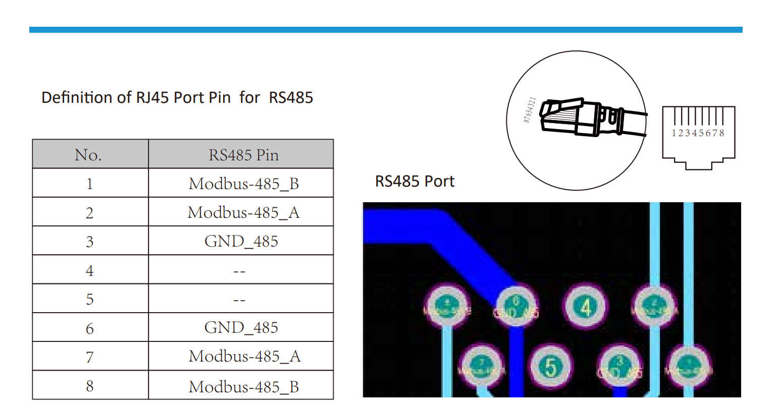
RS485
RS485 Wiring
- For correct RS485 wiring: Follow the guidelines for RS485 wiring.
- If the wiring shown in the table below is incorrect, please let us know.
- There is no general consensus in the industry about the usage of A and B for the RS485 polarity, so it may be counterintuitive and opposite of what you might expect for some devices.
| Device | SmartgridOne Controller model OM1 | SmartgridOne Controller model IG8 | RS485-USB converter | RS485-Ethernet converter |
|---|---|---|---|---|
| Pin 1 / Modbus-485_B | RS485 A | RS485_POS | RS485 A | TX+ |
| Pin 2 / Modbus-485_A | RS485 B | RS485_NEG | RS485 B | TX- |
| Pin 3 / GND_485 | RS GND | GND | Not available | G |
Configuration
NOTE: RS485 Device Addresses
- You MUST give each device on the RS485 bus a unique address. Check the manual of the device on how to do this.
- Use lower addresses first (1, 2, ...) because the SmartgridOne Controller will find them faster!
- For each device, it is generally recommended to stick with the factory default baud rate, parity, and stop bits. The SmartgridOne Controller will scan on those first.
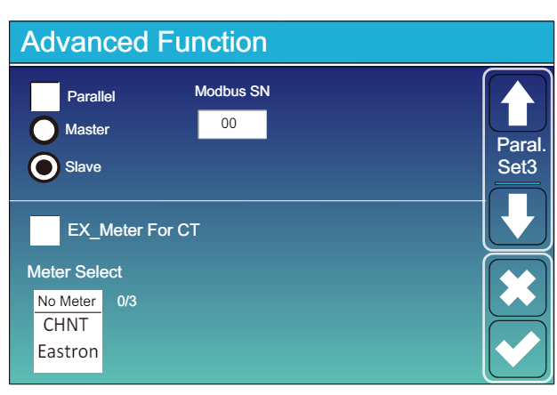
Allez à “Écran principal” >> “Paramètres du système” >> “Fonctionnalité avancée.”
- Le SN Modbus doit être réglé sur un nombre entre 1 et 247. Ne sélectionnez pas 0 !! Notez que s'il y a plusieurs appareils sur le bus RS485, chacun doit avoir un numéro unique. C'est l'adresse.
- L'option "Esclave" doit être cochée.
- Seulement lorsqu'un compteur supplémentaire est connecté directement à l'inverseur, "EX_meter For CT" doit être coché. S'il n'y a qu'un compteur en parallèle avec le SmartgridOne Controller, cela doit être décoché.
- Assurez-vous que les paramètres suivants sont tous corrects : "Max A Charge", "Max A Discharge", "Ampère de charge du réseau"